Among other interesting functions, AutoCAD Raster Design has some possibilities to rectify raster images through well-known function Rubbersheet that enables two basic methods of rectification (triangular and polynomial). As far as I remember from my photogrammetry courses there are also other methods to do these things and there is general misunderstanding of theoretical background of two above mentioned as well. So the question is:
- how do these methods work; what are they useful for?
- where do they belong in the wide field of raster data processing?
I am talking about raster data in 2D space appropriate for aerial photo and map canvas rectification. General overview is following:
Linear (also linear conform) method
Description:
The most simple method with no distortion or rotation of the image. Parameters needed are: insertion point and a scale of image.
Requires 2 control points and the typical example of use is rectification based on world file (eg. jgw)
Raster design use:
1. The use of world file via Image > Insert
2. No need to use Raster Design. The same result given by common AutoCAD command IMAGE (Xrefs dialog box).
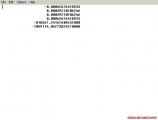
| Fig. 01 and 02. Schematic example of linear rectification and preview of world file content. |
Affine method
Description:
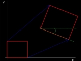
Possible affine transformations are: shift/move, rotate, scale, skew or any combination of them (Fig. 03). Those changes are applied on whole image homogenously without any local distortions (in the case of their occurence – eg. paper plan local deformation as a result of moisture -there is no way to rectify them localy).
Requires at least 3 control points and the result is always only “best fit” spatial aproximation.
Raster design use:
1. Image > Correlate > Match/Displace/Scale/
2. No need to use Raster Design but standard AutoCAD commands ALIGN, MOVE, SCALE etc…
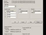
3. Insert > Image Manager > dialogue box enabling to specify insertion, scaling and rotating the image (Fig. 04).
| Fig. 03 and 04. Schematic example of affine rectification and vanilla AutoCAD dialogue box for affine insertion of raster image. |
Polynomial method
Description:
The same as affine transformation but with one important difference: the scaling of axis X and Y is independent (1. degree polynomial) and there is possibility to achieve local rectification (2. and 3. degree polynomial). Local transformation is calculated by the least square method or the polynomial regression. There are theoretically no limit for higher degrees of polynomial method but usually they are not used.
The result strongly depends on degree and always will be more or less the aproximation of control points location. The result qualifies this method to be called “rubbersheeting”. Lines are rectified into lines (1. degree) or parabolas (2. degree and higher).
This method requires at least 4 control points (1. degree). The control points number for higher degrees should be calculated with formula NP = (NxN + 3N + 2)/2 (where NP = number of points; N = polynomial degree). Consequently there are at least 6 points needed for 2. degree and at least 10 points for 3. degree. The more, the better.
Raster design use:
Image > Correlate > Rubbersheet > polynomial method. Apart 3 points rectification there is error result of spatial algebra (root mean square error) for control points. Degree of polynomial method available. Control point pairs are coupled by mouse clicking and signed by corresponding numbers.
| Fig. 05 and 06. Schematic example of polynomial rectification and Raster Design dialogue box for corresponding raster processing. |
Triangular method
Description:
Once again – I am not talking abou 3D! This method uses Delaunay triangulation in planar space (2D). During the triangular rectification, control points pairs are coupled spatialy exactly and triangles between them stretched and squeezed to fit by calculating the polynomial coefficient of each triangle. This is the most precise method with potential imperfections only “inside” the triangles.
The negative aspect is the fact that space ouside of triangles is not included in final result (raster cropping of convex hull).
Raster design use:
Image > Correlate > Rubbersheet > triangular method. Control point pairs are coupled by mouse clicking and signed by corresponding numbers.
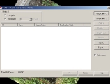
| Fig. 07. Dialogue box for triangular raster processing in AutoCAD Raster Design environment. |
Projective method
Description:
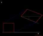
Familiar in single image photogrammetry. Central projection of an object from one to another planar placement. There is crossratio preserved and lines are always projected as lines.
Raster design use:
No appropriate tool for this rectification method neither in Raster Design nor in AutoCAD.
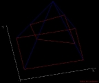
| Fig. 08. Schematic example of projective rectification method. |
Discussion and conclusion
There is possibility to achieve all kind of rectification methods by Raster Design tools except of the projective one. This means that Raster Design could not be used for single image fotogrammerty (has no function for projective lens distortion).
The border between affine and polynomial rectification is not always precisely recognized. Indeed I have met the terms “affine polynomial 1. degree” and Raster Design itself allows polynomial 1. degree with only 3 control points with no residual error – that means pure affine transformation.



[…] wrote a short item about raster rectification issues a month ago. The projective method mentioned at the very end of the article was designated as problematic in […]